Pinball Machine
This was a class project for a rapid prototyping class at UCSD, for which we designed and built our own pinball machine. This was the most intensive prototyping project I’ve ever done, and it was a ton of fun. I want to log my thought process for everything I did here, and my takeaways from the process.
System Overview
The overall machine has the following features:
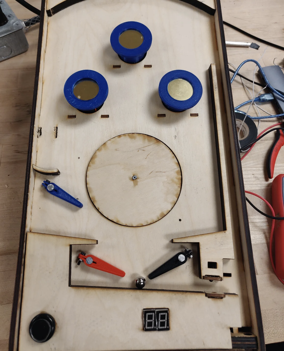
- three bumpers
- two paddles
- a scorekeeping system
- buzzers for music
Paddles
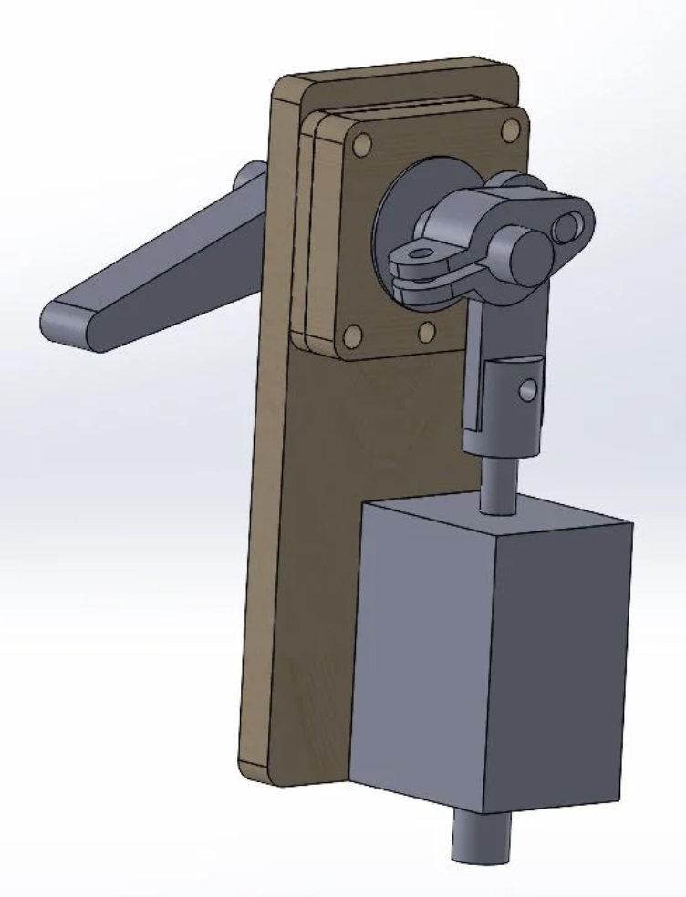
We had two main options to make parts of our pinball machine move - either use a motor, which we only had cheap versions of, or use a solenoid, which was more powerful but moved linearly instead of rotating an axis. Since we only needed the flippers to have one of two states (up or down), we decided to use a solenoid. This meant that I would have to design a mechanism that would convert the solenoid’s linear motion into a rotational motion that would rotate the flipper.
The mechanism that I ended up creating involves a piece that would be secured to the solenoid through its provided screw hole, which had a rod sticking out one end that would slot into another piece that would be secured around an aluminum rod. As the solenoid moves up and down, this piece would move the second piece up and down, but since it was secured to the rod, it would rotate the rod. The flipper is placed on the other side, and rotates as the rod rotates. Initially, I had pieces that would just fit on the rod and hopefully keep the same rotation as the rod through friction, though after testing I discovered this was not enough, and added two flaps on one side of both the rotating linkage and the flipper so that the hole could be tightened using a screw.
On top of designing this mechanism, this was also the first time I learned how to use assemblies in Solidworks, and it was an incredibly useful tool to help me visualize the thing I was making.
Score Display
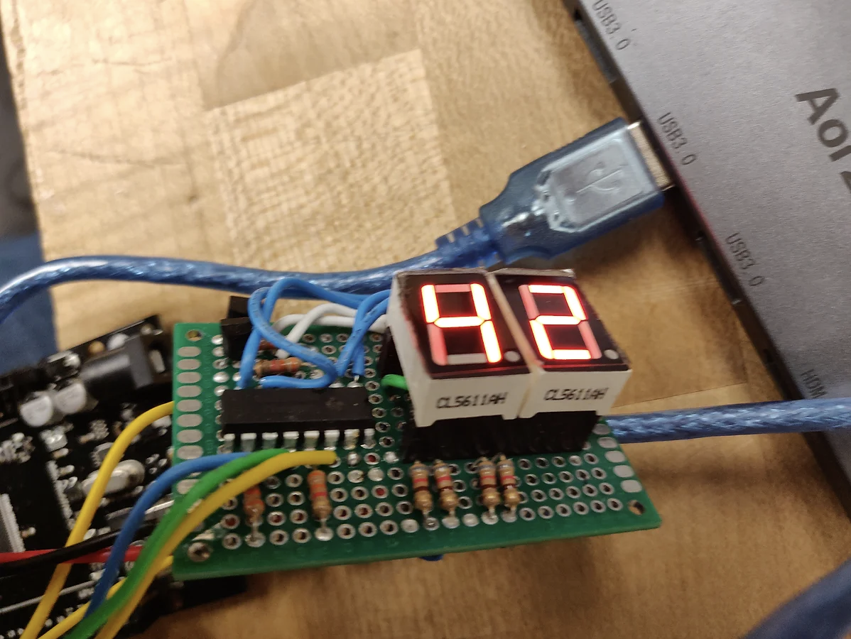
As an exercise for the class, we were not allowed to use our control board to power each segment of our score display, and instead we were told to use a shift register, which can be written into using only three inputs. On top of this, we were also tasked with using this one shift register to power two displays at the same time, the challenge coming from the fact that there are only eight outputs. I ended up using two transistors to turn the power supply on and off between the two very quickly, and write values to the shift register so that it would seem as though two different numbers would be displayed at the same time.
Since I wanted this to be its own standalone circuit, I also took the time to solder all of these components to a perfboard (a circuit board covered with holes), and all in all the entire process took me about five hours. I learned that picking the order in which you solder the wires is extremely important so you don’t crowd yourself out later on in the process, and that it is also extremely important to make sure you don’t touch electronic components with your soldering iron for too long so you do not cause permanent damage. I also discovered that the header pins were too thin, which would lead to numbers not displaying properly due to bad connections, so adding solder to thicken these helped a lot.
Bumpers
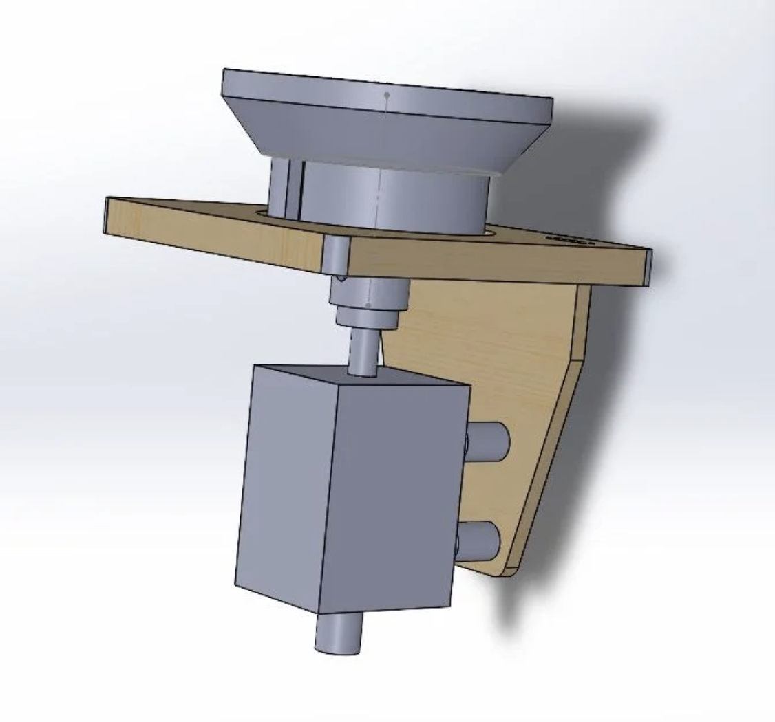
I also designed a bumper, which, when touched by the ball, would pull a shield downward, launching the ball away from the bumper.
I first researched how traditional pinball bumpers worked in order to get a sense of what would go into building one. Traditional pinball bumpers work using a skirt with a downward extension that gets tilted when the pinball rolls on it. This depresses an electrical contact, completing a circuit, which activates a solenoid below it. While this particular mechanism was really interesting, I knew it would be far beyond my manufacturing capabilities to produce, so I had to make something simpler.
My first idea was simply using copper tape - have a positive end on the bumper itself, and the negative side on the playfield. When the ball touches the bumper, it connects the two pieces of tape, completing a circuit, which can be used to trigger a solenoid. While this would work, I wanted a more elegant solution that did not involve putting copper tape onto the playfield, so I would be able to use this mechanism in different playfield designs.
The second idea I had was to use a piezoelectric sensor - a device that would trigger a signal when vibrated. I would need to design a housing to encase the sensor so that whenever the ball bumped against the housing, the sensor would be triggered. This signal, after amplification and processing, could be picked up using an Arduino, which would then trigger a solenoid. I ended up going with this idea, since it required no modifications to the playfield in order to work, and I thought that the concept was more interesting.
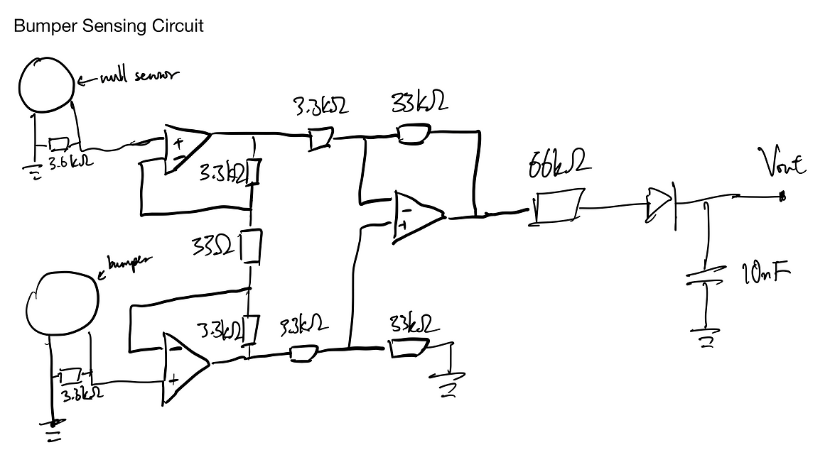
I went through several iterations of a design that had two halves that could be screwed together. The sensor would be wedged between the two parts, and the whole thing could be bolted to the solenoid, which would move the entire assembly up and down. To eliminate noise from, say, the player accidentally jostling the machine, I used an instrumentation amplifier to take the difference between readings from the sensor inside the bumper and a null sensor placed somewhere outside, meaning that if something affected the bumper and not the null sensor, a signal would be produced.
My first iteration was too large for my desired playfield, since the sensor was also too large, so I made it smaller by cutting off the plastic rim around the sensor. I also increased the slope of the piece that would contact the ball, since from my testing, the ball did not get repelled fast enough.
Sensing Electronics
This course has taught me a lot about creating filtering circuits to create robust sensors. There are two main sensors on this pinball machine: two optical sensors to sense if the ball enters a certain location, and one on each bumper to detect if the ball gets hit. Operational amplifiers (or op-amps) are extremely important for these circuits, and have so many uses that I’m not going to get into here, but the important thing to know is that if you uses correctly valued resistors and connect them in the right way, you can create trigger circuits that output a fully on or fully off signal, or amplify a signal with low-amplitude so that it can be more easily detected. Circuit diagrams are added below.
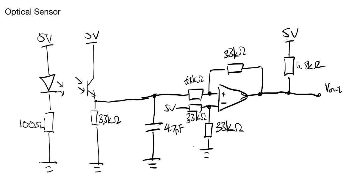
The way my partner and I designed our optical sensor arrangement is that when the ball rolls between the IR transmitter and receiver, it blocks the transmitter and decreases the voltage at the input to the op-amp. The op-amp is set to either output 5 volts or 0 volts depending on the level of the input, which cleans up the signal so that the microcontroller can more easily detect whether a ball is there or not.
The biggest challenge with the bumper sensing circuit is that I didn’t want it to trigger if the player happens to jostle the machine, so I decided to implement an instrumentation sensor. This is an arrangement of 3 op-amps that takes the difference between two sensors, so that theoretically, if both sensors were triggered at the same time, the resulting signal would still be consistently at 0V. The combined signal is then amplified, and connected to a peak detector in order to smooth out voltage peaks that occur in quick succession, which prevents the microcontroller from registering multiple hits (ideally I would add another trigger at the end of this so that it either outputs 5V or 0V, but I was short on time and didn’t want to do the calculations).
Software
All of these electrical subsystems are controlled using a single Arduino Mega. This simultaneously handles bumper states, score keeping, and tracking the state of the game (whether the bumpers and paddles should be operational or not). The code can be found here.